Inspection at the speed of your production line.
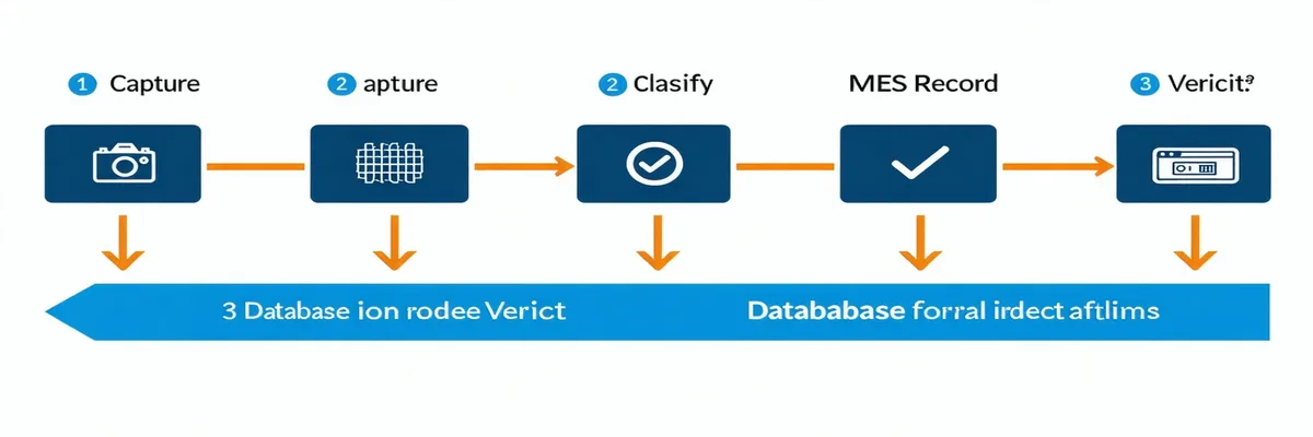
Camera captures. Model classifies. MES records. All in under 200ms per part.
Four steps. One continuous loop.
Each step is designed to complete without adding latency to your production line.
Hardware setup and mounting
Eolvision engineering configures the camera station for your line. Camera type (2D area scan, 2D line scan, or 3D structured light) is selected based on your conveyor speed, part size, and defect type. IP67-rated enclosures are used in washdown or dusty environments. Mounting brackets are custom-designed to your conveyor geometry — no line modification required.
Model training on your parts
Eolvision builds a defect classification model specific to your part geometry and defect catalogue. You provide images of known-good parts and known-defect parts from your production line. An active learning loop prioritizes the most informative images for labeling. Typical time from image collection to first live deployment: 2–4 weeks.
Training data required: 300–1,200 labeled images across defect categories. Eolvision provides labeling tooling and guides the process. No machine learning expertise required from your team.
Real-time inference and verdict
At runtime, the camera captures each part as it passes the inspection zone. The Eolvision inference engine classifies the image and generates a verdict: Pass, Fail, or Review. The verdict is output simultaneously on three channels: a 24V discrete I/O signal to your reject station, an OPC-UA or Modbus TCP write to your PLC, and a structured data record to your MES.
Part meets all inspection criteria. Conveyor continues.
Part does not meet criteria. Reject station triggered.
Borderline case. Flagged for human review queue.
Dashboard, trending, and QC records
Defect images, reject counts, and inspection metadata accumulate in the Eolvision dashboard. QC managers can view reject rate trends by shift, production run, part number, and defect type. Records are retained per your configured policy and can be exported for IATF 16949 audit documentation.
Inspection speed by camera configuration
All latency figures are end-to-end: from camera trigger to verdict output on the PLC discrete I/O signal.
Benchmarks measured on Eolvision production deployments. Actual latency depends on image resolution, part complexity, and server hardware. Contact us for a line-specific estimate.
Ready to see it on your line?
We bring the hardware to your facility. You run the demo on your actual parts, your actual defect types.